Notes on converting home
sewing machines to long-arm
Monday, 01.21.2019
Source Material
This note is intended to supplement the YouTube video and
blog posts of Ms Anne Marie Sullivan.
She wanted a long arm, and did not let her lack of knowledge in
mechanics or welding stop her. She used
common sense, YouTube videos, and apparently
a little help from her more mechanically/electrically inclined son, and
she prevailed. We should all be so willing and determined.
https://youtu.be/tNOe6cDudlY?fbclid=IwAR2xTGZaF9OJ0y08iPF-1pTiT2RrWxjPwyFUfXr78ReJ
RkVf28GnaYurSV8 The
finished machine in action.
https://amscreates.blogspot.com/search/label/making%20a%20long%20arm her
blog, with a LOT more detail.
I HAVE NOT TRIED ANY OF THIS ON A REAL SEWING MACHINE; this
note based on 35 years of engineering
experience on ships and boats, and 5 years of fiddling with sewing machines.
I suspect others have done this - I haven’t found their web
pages or their posting in bulletin boards.
Machines to hack
Old Singers
What we’re after is a cast iron, straight stitch machine.
Old, but not TOO old (1920 to 1950 is the sweet spot). Singers were high quality, made in large
quantities, and parts are readily available; in my view they should be your
first choice.
1.
66. This is what
Anne used. This was the top of the line,
the biggest machine Singer made, from the 1910’s into the 1950’s.
2.
99. Slightly
smaller, but if we’re stretching it anyway, who cares? More commonly available, may be a little
cheaper. Mechanically almost
identical. Roughly the same vintage.
From 1911 to 1958. http://www.singersewinginfo.co.uk/99k/
3.
201. Replaced
the 66, and acclaimed as the best straight stitch machine ever made. 1929 to
the early 1960’s. Up until 1951, they
were cast iron, later models were aluminum.
Mechanically, the later machines were very similar, but the styling was
more angular, and they were MUCH lighter.
4.
15-91. “Potted”
gear drive motor like the 201s. 1930’s
to the early 1950’s. The very similar 15-90 has a belt drive motor and would be
another good choice.
5.
There are OLDER Singers (15, 115, 27, 28, 127, 128,
“New Family”) but they were generally treadle machines from the start, although
sometimes converted to electric motors and they sometimes take weird needles
and bobbins; I’d leave them alone, with the possible exceptions of the 127 or
128. There are LATER Singer Straight
stitch machines (the 301 comes to mind) but they are NOT Cast Iron, and they
are such nice machines on their own, I
wouldn’t chose one to hack. Most later
Singers (all the other 300 series, 400, 500s)
used cast aluminum chassis, and had zig-zag, making them harder to
convert. There is a myriad of Singer
industrial machines (95s, 96s and MORE) that might work, but they are even
heavier than the cast iron home machines, and parts are harder to find, but
they stitch up to 4200 stitches per minute! (home machines are lucky to break
1000).
Old Singer CLONES
There are tons of generic Singer clones (the 99 being the
model most likely to be cloned). Some are American (Sears Roebuck carried
Singer clones from various manufacturers) european, others Japanese (well into
the 1950’s). Again, you want cast iron,
straight stitch.
Other vintage machines
Ideally, you’d like a cast iron, electric, straight stitch
machine, that uses bobbins and needles you can easily get, and an arm that at
its narrowest point is round, or nearly so. Something from the 1920’s to the
1950’s.
There are only two sizes of needles that are EASILY
available, the 15X1 (AKA 130/705H) used on anything evenly remotely modern, and
the 206X13 size used on some Singers (Singer 306, 319, 320). 20X1 you can get New Old Stock from specialists on E-Bay, or you can set a
15X1 low in the needle clamp
Here is a needle list for damn near every machine ever
made; it’s perhaps best to avoid anything that uses anything but the 3 sizes
just mentioned: http://ismacs.net/needle_and_shank/pdfs/ismacs-needle-list.pdf but
for the brave, Treadle Lady on E-bay has has both New Old Stock and brand new needles
in a few other sizes. https://www.etsy.com/shop/TreadleLady?ref=l2-shop-info-avatar§ion_id=12034501
Bobbins - almost any size/shape of the typical modern short
cylindrical bobbin will work and seem to be pretty easy to find (Class 15,
Class 66, etc); “long” bobbins used on shuttle machines are far harder to find,
but they are out there, try E-Bay or https://shop.sew-classic.com/Shuttle-long-Bobbins-Singer-27-127-28-128-others-5-Pack-SC
BN8228.htm
White was one of the biggies, and they made machines for
other marketers like
Montgomery Ward and Sears Roebuck. Goodrich, National, Domestic, New Home are a
few other brands. Presser feet and other
parts will be harder to come by, but E-Bay is your friend.
Welding
Welding cast iron is considered a little sporty, compared
to welding steel, but the parts we’re concerned with are very lightly loaded,
and the strength considerations people repairing engine blocks and cylinder
heads worry about matter not. TIG is
nice (what Anne used) but the equipment is expensive, and it needs shielding
gas. MIG would be OK, even with flux core wire and no shielding gas, and you
can get cheap MIG setups from Harbor Freight and/or Canadian Tire. For these methods, it’s best to use a rod or
wire with a high Nickel content (ERCuAl-A2 is one such), and a
little pre-heat would not hurt, but ordinary
consumables MIGHT work for this non-critical application on clean metal. For stick welding try https://www.muggyweld.com/product/exhaust-manifold-repair-kit/ their special rods are designed for this
application. Gas BRAZING with Aluminum
Bronze filler and the appropriate flux will work as well, or you can TIG with
this filler.
For welding the pipe to the head/body, take a look at weld
joint diagrams, and think “fillet weld” or “Lap Weld” where the pipe (NOT
Galvanized!) is jammed onto the body of the machine. https://en.wikipedia.org/wiki/Fillet_weld
Don’t skimp on filler metal. You’re going to grind the top of the bed flat
afterwards, and you don’t want “undercut” anywhere.
It MAY be possible to weld, braze, or solder an aluminum
(or, “pot metal”, an alloy with a lot of Zinc in it for lower melting point,
but good mechanical properties) machine; the Muggyweld people have products
that might work if you must go there, most welding supply places will have
other ideas/products. TIG or MIG might
work, Stick welding WILL NOT. Anne
didn’t to it that way, and I haven’t either.
Metal for the bed plate
Most big box home stores carry mild steel in various sizes
(¼” thick is plenty), but often not wide enough, as Anne experienced. Most larger metropolitan areas have a steel
supply place that will retail small quantities. Try “Metal Supermarkets” (a national/Canadian chain, https://www.metalsupermarkets.com/) and ask if they have any
“drops”, the scraps from cutting or shearing plate to suit particular sizes
OTHER customers needed. “Drops” will be cheaper than cutting the chunk you need
from a “stick”, you might even get them for free. “Hot Rolled Steel Plate” is
about what is wanted, but “Strip” or “Cold Rolled Steel” are other words to
suggest. Steel fabricators or welding
shops are other possible sources for suitable “drops”.
A rib under the bed would be nice. You could get this by
cutting the web of an I-beam to get your bed, or by welding two L-section
pieces of steel together back to back, or an L and a flat plate.
Extending the shafts
See what shafts we’re on about: http://ismacs.net/singer_sewing_machine_company/images/singer-66-oiling-diagram-1.jpg
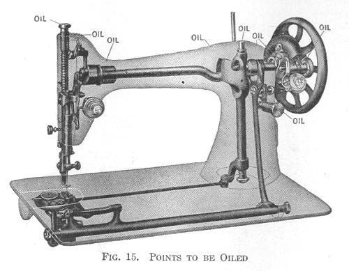
The upper shaft is the big deal. The slender rear shaft under the bed drives
the bobbin, and the bigger shaft in the front of the bed drives the feed dogs;
both of the under-bed shafts oscillate rather than rotate, on 66s at
least. Rotary hook machines, the bobbin
drive WILL rotate.
You may be able to find the right diameters in the same
rack at the big box store you find the steel plate, or try these sources:
2.
The aforementioned Metal Supermarkets
3.
Grainger, McMaster Carr - industrial hardware
stores. They have extensive on-line
catalogs, but also local stores in many areas.
4.
Distributors of small mechanical/drive parts, like http://www.sdp-si.com/products/Couplings/index.php
If you are working with a European or Japanese machine,
you’ll likely need metric shafts. A cheap
Harbor Freight digital micrometer or dial caliper will help figure this out.
IF you cannot pull the shafts out completely and replace
them with longer numbers, you will need couplings. They should be “rigid” or “sleeve”
couplings. Very well stocked hardware
stores MIGHT carry them, or numbers 1, 3 or 4 above. https://www.grainger.com/category/power-transmission/shaft-couplings-collars-and-univer
sal-joints/rigid-couplings?attrs=Material+-+Couplings%7CSteel~~System+of+Measurement
%7CInch&filters=attrs for examples. It looks like Anne fabricated her
own. Even if you CAN pull the upper shaft for instance, machining (flats,
splines, keyways) at either the handwheel end or the needle bar end may make a
one piece shaft beyond your skill level. Anne’s method of cutting the shafts in
half and using two couplings will work no matter what configuration you find.
You could also solder or braze a close-fitting piece of
pipe or tubing OVER the shafts to be joined to act as a coupling.
WIth a tight fit (less than .010” difference between the
outer diameter of the shaft and the inner diameter of the sleeve) and a lot of
overlap between the sleeve and the shaft, you might even be able to get away
with using epoxy or cyanoacrylate (“Super”) glue to glue the couplings to the
shaft. https://www.jbweld.com/ or Loctite Retaining Compounds (638, 648,
660 or 680)
IF you are SURE you never want to use the feed dogs again
(commercial long arm machines don’t have them!), you could get away with NOT
restoring the feed dog shaft (Anne didn’t), going so far as removing the dogs
themselves out of the area of the needle plate/bobbin case, but consider that
having a huge harp to work a big quilt WITH
A WALKING FOOT might be an attractive option.
Anne drilled and tapped the existing bobbin shaft to extend
it.
Consider the SEQUENCE of re-assembly of the head. Do you
weld the pipe to the cast iron frame pieces FIRST, or after at least
dry-fitting the shafts?
Some design points
The use of shelf brackets to hold the head firmly in
relation to the bed is BRILLIANT. Anne
drilled and TAPPED machine screws , at least 2 for each portion (bed and head),
on both sides (no less than 8 total in other words). This step is absolutely crucial to a machine
that will sew properly when you’re done.
The “windows” in the top of the pipe are to work the shaft
couplers. You may not need them if you
can source a one piece shaft long enough to span your new arm, or you may need
only one.
Use a thread locker (Loctite or it’s equivalent) on all
threaded fasteners for your lengthened shafts when you final assemble your
machine.
Anne’s machine is set up with a toggle switch (looks like
an IKEA floor lamp switch) and what seems to be a fixed resistance to drive her
machine at a relatively slow, constant speed.
I have no details on how she did it; she implies her son helped her on
that point. Older electric machines use a big variable resistor to alter the
voltage being fed to the motor. A big wire wound or carbon FIXED resistor could
be used, or you could McGyver something up by adding a switch in line with the
existing foot controller that you mechanically set to a comfortable speed.
I would cut the head at the narrowest part of the neck, and
chose a pipe or mechanical tubing that fit over this neck, with a little bit of
clearance, so that the cast iron machine pieces fit INTO the pipe/tube at least
a half an inch.
Timing the machine
HOW to time the machine is beyond the scope of this note; I
just want to emphasize its importance.
Timing is the relationship between the action of the bobbin case or
shuttle and the needle. Get it right,
and you have nice stitches. Get it
wrong: no stitches and/or broken machine. Anne describes the agony she went through
to get this right. https://www.google.com/search?q=hook+timing+sewing+machine&oq=timing+sewing+mac
hine&aqs=chrome.3.69i57j69i60j0l4.30799j1j9&sourceid=chrome&ie=UTF-8
http://www.parts.singerco.com/IPinstManuals/66.pdf
Most online tutorials deal with rotary hook machines (Most
post WWI machines). If you have an
oscillating hook or a shuttle machine, you will have to look harder to find
help if the timing is off. Try http://ismacs.net/ or Facebook vintage sewing machine pages.
You can also try and preserve the timing of your machine
before you cut it in half by “match marking” the body and the shafts in a set
position of the hand wheel, say, Top Dead Center with the needle as high up as
it will go. Preserve the relative
relationships of your “Match Marks” (on BOTH ends of the upper shaft in
particular) and you should be at least close. I want to thank, Ryan for his great work on writing this up.
No comments:
Post a Comment